Linked here is my Resume for 2023.
Author: sam
The Wildflower Botanical Orchestra performs – The Sun Stands Still
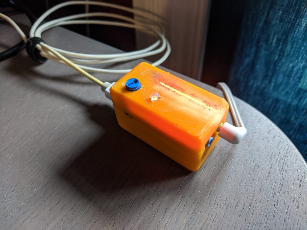
This musical piece is performed by the resident plants of the Wildflower Botanical garden, using sensors to track the changing biological states of the plants over <35> days through the Winter Solstice (November 25th – December 31st). On these shortest days of the year, the Sun stays lethargic all day on the horizon, for hours appearing to stand still. This Biodata Sonification installation will utilize orchestral instrumentation to create an interactive soundscape distributed through the Lady Bird Johnson Wildflower Center, allowing guests to listen to the invisible biological changes occurring within plants. Find out more about how this system functions at electricityforprogress.com/biodata-sonification/
Biodata Sonification is the process of extracting real time biological information from living plants and translating that complex information into sounds which a guest can perceive. This installation creates a series of ‘Biodata Sonification Nodes’ which will be connected to the leaves of a plant using sticky (non damaging) electrodes and each plant will perform one instrumental part of a larger musical piece.
As multiple plants are connected to these ‘Nodes’ a larger musical piece will begin to unravel, telling the story of each plant’s day in the garden, providing guests with a variety of plants and instrumentations to focus on. While the raw presentation of data from the plants may not necessarily sound like ‘music’, the biodata can be partnered with the sounds of specific instruments and filtered to play in specific keys and note ranges chosen by a composer.
During this incredibly challenging pandemic the public has been pushed far from art in exhibition and installation. But this distance can and should be overcome. By utilizing our existing technology infrastructure and providing guests with safe remote options for viewing and interacting with installation artwork, we can break through the physical isolation and help guests find connectedness, curiosity, and wonder. It is critical at this time to provide the public with engrossing, interactive works of art, and provide them with solace utilizing the revitalizing natural splendor of living plants in botanical gardens.
Components
- Biodata Sonification Nodes will connect to four selected plants. The nodes will contain a Biodata Sonification device and a MIDI sound synthesizer. Speakers connected to each node will present the sounds.
- Using RTP MIDI connectivity, each biodata sonification unit can be interconnected using Wifi, streaming the MIDI data to local and remote users. This feature would require a local (or mobile) wifi network with internet access.
- A Placard by each plant describing the biodata sonification process with link to the eforp biodata page
Goals and Objectives:
- Provide a detailed study of the changing biological processes through real time data feeds and durable recording of the installation
- Provide an immersive and interactive experience for guests both in person in the garden (and remotely through an interactive content site on the internet)
Risks
- No internet access – this will limit the usage of wifi MIDI for remote user interaction and archival purposes.
- Pandemic considerations may likely allow no visitors into the garden space
Everyday Calendar – Hacking
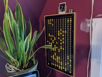
The Everyday Calendar by Simone Giertz is a personal affirmation system where a user makes a daily goal and is presented with a series of hexagonal copper numerals which illuminate when touched. By modifying the open-source code, a user is able to hack the Everyday Calendar into a matrix display and touch surface. The hardware is highly responsive, and minor tweaks to the example code and api can easily yield results. For this hack I have used implementations of Conway’s Game of Life and (of course) Tetris to display on the calendar, and to use the buttons as input for controls and parameters.
Simone is planning to make additional units and you can sign up to be notified about the continued project at: https://www.simonegiertz.com/every-day-calendar
Caution – beyond lay dragons – I can not stress enough how easily one can mess up when programming, and bricking this bootloader would be a sad day indeed, so be careful and follow arduino programming best practices
- If you are a beginner, do beginner tutorials first, flashing an LED may seem simple but it is the basis for all digital processing and user interface.
- Always select the correct ‘Board’ and ensure all other parameters are set, if you mess this part up you could brick your device! This project uses an ATMEGA328p at 3.3v and 8Mhz crystal. Checkout Simone’s detailed instructions on choosing the ‘Arduino Pro or Pro Mini’, and find the primary codebase and libraries for the Everyday Calendar project.
- If you are an advanced user and don’t need to be reminded, please review steps 1. and 2.
Everyday Life – an implementation of Conway’s Game of Life
explanation, base code, how i did it, my code
Everyday Tetris – an ‘alpha’ version of gameplay on the Everyday Calendar
explanation, base code, how i did it, my code
Instagram Video
Youtube Demonstration
Project Parts
| Project Name | Boards | Parts | Notes |
| MIDI Filter 1U – Knob Lights | 5 | 1 built, 4 pots, need 5v ProMicro | Limited run |
| MIDI Filter 1U – Regular | 5 | 5v Pro Micro | |
| MIDI Filter 2HP | 5v Pro Micro | Board and face revision 3 ** | |
| Party FM | — | 3v Pro Micro, etc | finalize design |
| Party Breadboard 1U | fuses | ||
| Party Breadboard | |||
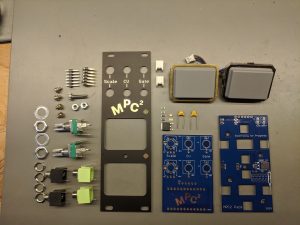
| Party MPC | — | Board and face revisions, mechanical stress, | |
| Party In Party Out | — | New Project for line level I/O for fx | |
| Party Gates (1U and full) | — | Some boards on hand, are they usable? | Finalize design for buttons, menus and modes |
| Party Button 1U Passive | 10 | Bournes x3 trimmer, thonks, Button and LED options/reversee | review front panel for both sizes |
| Party Button 1U RGB | 10 | ATtiny85’s, neopixels, buttons | review front panel for both sizes |
Party FM
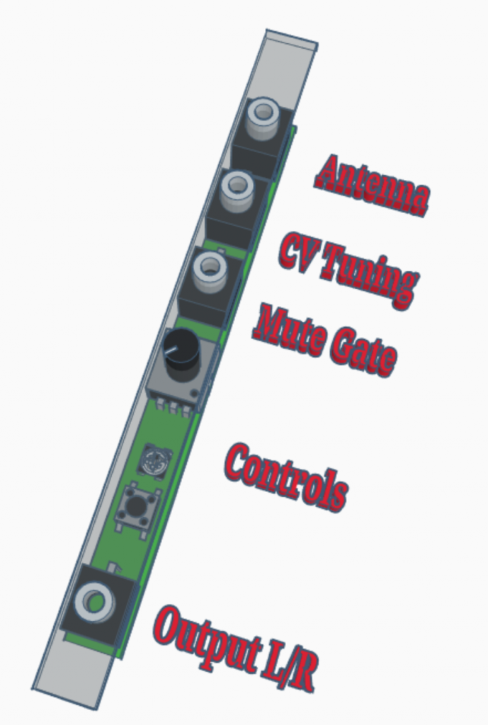
PartyFM Eurorack Radio Module


The PartyFM is a minimal FM radio module in Eurorack format. Implemented using the RDA5807M chip and library set this module:
- outputs mono
and stereo audio– force Mono - allows muting and tuning via CV input
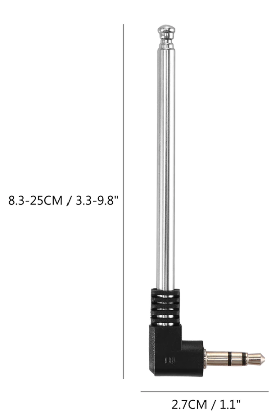
- expansion for antenna? Heck yeah
- Unit changes the radio station based on CV changes
- Knob with rgb LED and button
- allows coarse and fine tuning (press and hold button while turning, or press for modes).
- Tuning might not be smooth, and could be digital and jarring (testing!!)
- turn off ‘softmute’ which mutes weak signals
- Panic reset function?
Hardware using Arduino proMicro brain and generic breakout board with RDA chip and crystal, neopixel led indicator, selection knob, and tactile switch. CV Tuning input, Mute Gate input (L/R), output L/R, stereo indicator led.
API sourced from marthertel.de
http://mathertel.github.io/Radio/html
Choose the chip you have in your setup and see what functions the library supports.
| Feature | TEA5767 | RDA5807M | SI4703 | SI4705 | ||
| RADIO | band = FM | X | X | X | X | |
| band = FMWORLD | ||||||
| freq | X | X | X | |||
| mono | X | X | X | X | ||
| stereo | Decode stereo signal | X | X | X | X | |
| RSSI | signal strength indicator | 0 – 64 | ||||
| softmute | X | X | X | |||
| mute | X | X | X | X | ||
| Seek | ||||||
| FM Grid | 50 kHz | |||||
| Audio | volume | Supported number of volume levels | 0 – 15 | 0 – 15 | 0 – 63 | |
| bassboost | Boost bass frequencies | X | – | – | ||
| RDS | Data | Decode RDS signal | – | X | X | X |
| Errors | Provide information on RDS signal errors | – | – | X | X |
Protected: Circuit Board Orders
Party Breadboard 1U
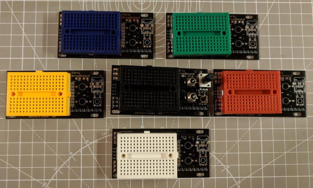
The same great prototyping experience of the full sized Party Breadboard, in super cute 1U format! Use this to spin up a quick schmidtt-trigger or 555 timer oscillator, try out a distortion circuit, or pop in a bunch of LEDs for a blinkenlight party! Available in both Pulp Logic and Intellijel formats, this board is made to fit many skiff. Purchase the Party Breadboard 1U in my store, and checkout the full sized Party Breadboard!
WARNING this module exposes dangerous voltages from the power supply +12v, -12v, +5v) and can easily cause serious electrical problems, short-circuits, or could blow out one of your modules! Well, really it’s not much worse than having a loose patch cable jacked out of a CV and banging around. Be very Careful!

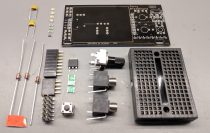
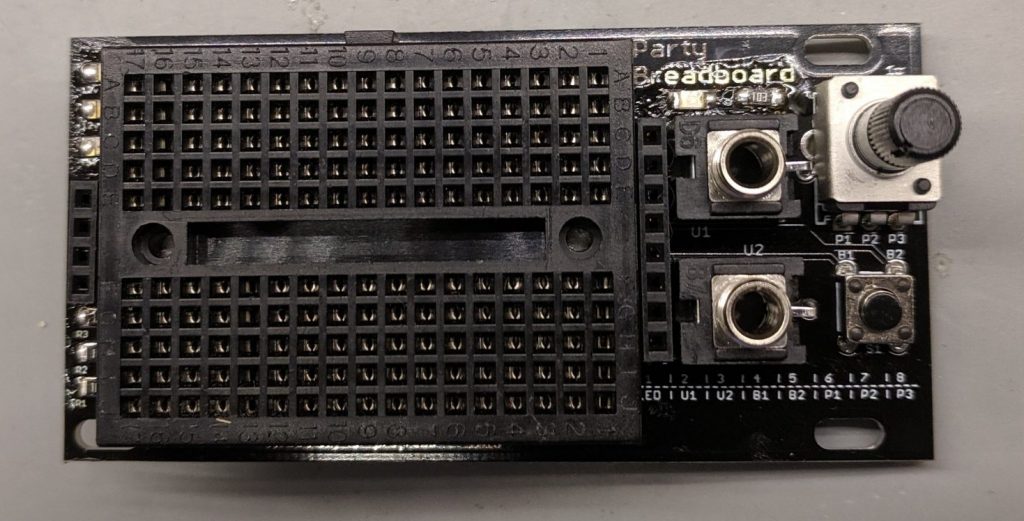
In this DIY build users have a variety of I/O options. The included three 3.5mm jacks easily allows signals to be patched across other modules. Along with an onboard indicator LED, the board also has footprints for a variety of mini and 9mm potentiometers, allowing many different trimmer and small pots to be used. Finally a tactile switch sits to the bottom right corner.
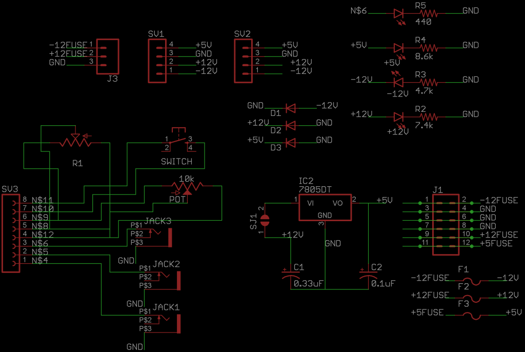
Each of the I/O can be interfaced using the 8 pin jumpers at the right of the breadboard with pin1 connected to the LED, U1/U2 connected to the tip of each jack (the sleeve is grounded), B1/B2 attached to each side of the tactile button and P1/P2/P3 connected to the wiper and ends of the potentiometer. A small legend for the pin connections is printed at the bottom of the module.
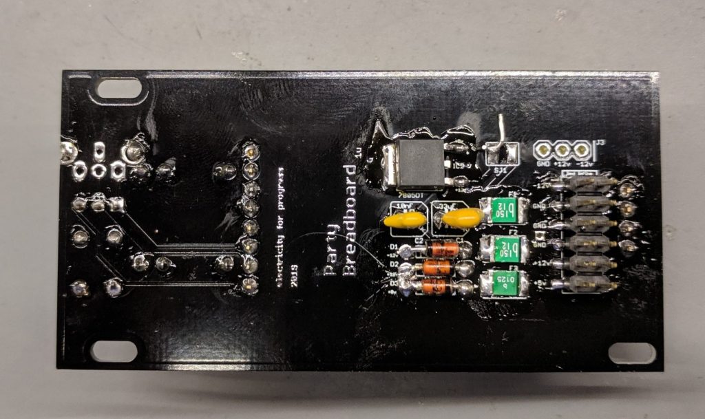
Power is provided on the back by a 10 or 12 pin connector, this should be a surface mount male header and you may need to ‘clip’ the small plastic tabs on header. The 5v rail can be engaged by closing the SJ1 jumper and including a 7805 regulator, or you can use 5v provided by the main skiff power supply using a 12 pin header. I tend to regulate my own 5v on each module, considering it is usually used for microcontrollers and sensitive devices. For protection there are include PTFE fuses on all three power rails (-12v,+12v,+5v) in order to manage short circuits and zener diodes to dump excess voltages.
The LEDs on the front panel each have their cathode (negative/flat side) towards the right side edge from the front face of the panel, the LEDs go through the current limiting resistors and then to ground. Resistor values can be chose to taste, many prefer very dim LEDs for their modular systems (especially ‘always on’ indicators), I use a 10k trimmer pot to test the brightness of the LEDs before installation into the board… testing and choosing the indicator LED brightness is a great first project to use the Party Breadboard! Indicator LEDs 4/5 allow two different color LEDs to be set with opposite polarity and makes it easy for a user to view the rough voltage (brightness) and polarity (color) of a CV signal.
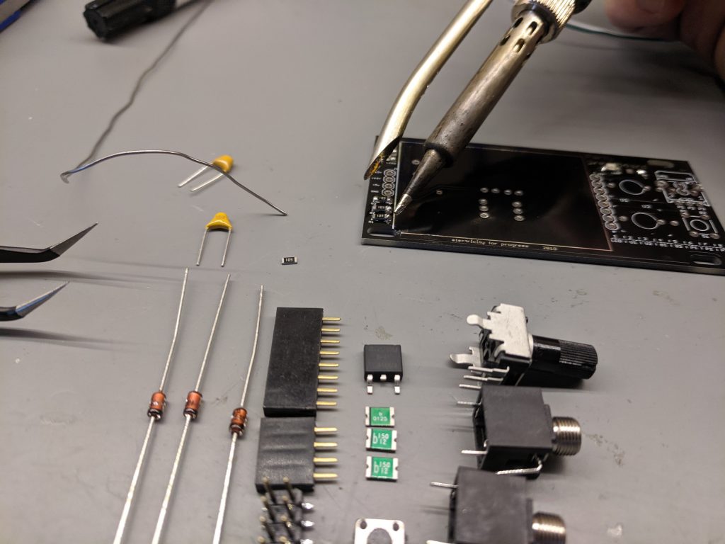
Diodes D1 and D2 are 12v zener with D3 being 5.1v. Similarly F3 is a 5v fuse and F1/F2 are 12v fuses. The 7805DT regulator is a SMD package, but any 5v regulator could be hacked on, be sure to close Jumper SJ1 with a piece of wire to power the 5v regulator! Two capacitors are included to clean up the power lines around the regulator, if you are using 5v from the modular case then these caps can be excluded as well as exclude the 7805 and leave SJ1 jumper open.
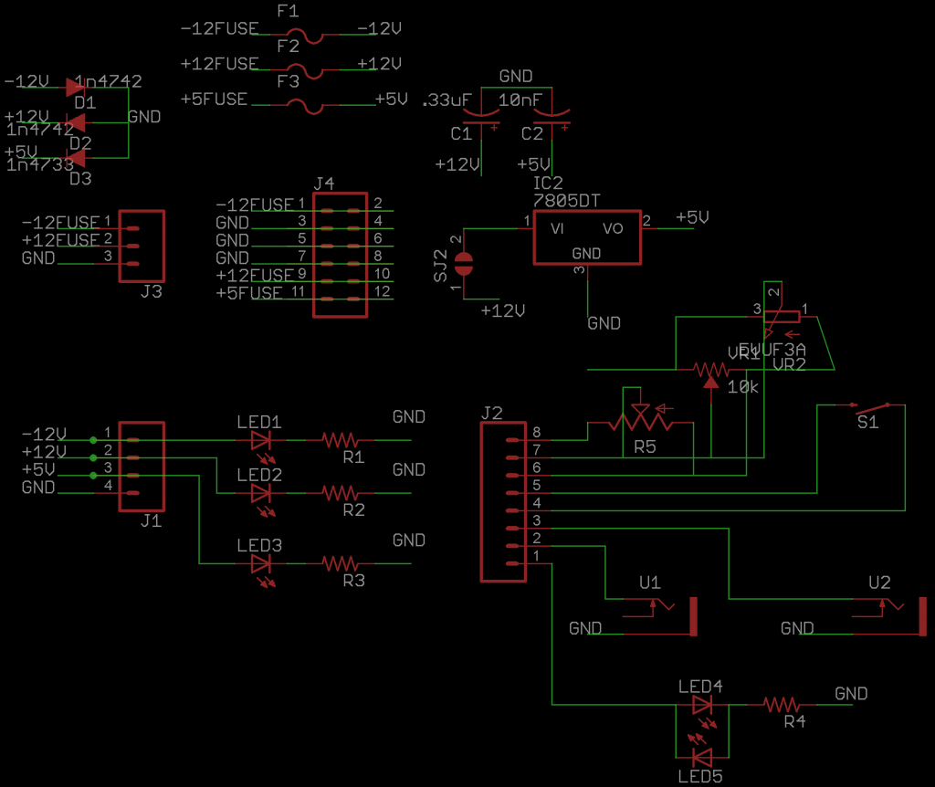
This Schematic shows the simple routing from the jumper points and the power connections.
Party Breadboard
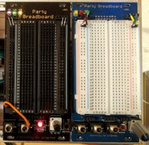

The Party Breadboard v002 is an electronics prototyping platform built into a 12hp (60.6mm) wide Eurorack format, allowing the exploration and design of custom circuits to expand a Modular Synthesis environment. When creating a new module or whipping up a quick LFO or blinkenlight, nothing makes the process easier than an integrated prototyping breadboard! Purchase the Party Breadboard in my store. Also available in super cute 1U format for Pulp and Jel systems!
WARNING this module exposes dangerous voltages from the power supply +12v, -12v, +5v) and can easily cause serious electrical problems, short-circuits, or could blow out one of your modules! Well, really it’s not much worse than having a loose patch cable jacked out of a CV and banging around. Be very Careful!
Printable-Instructions https://docs.google.com/document/d/1t_eVLtVa8f25B5C8VLIUo2R9oE2Kq5l0Wpl25trGX6w/edit?usp=sharing
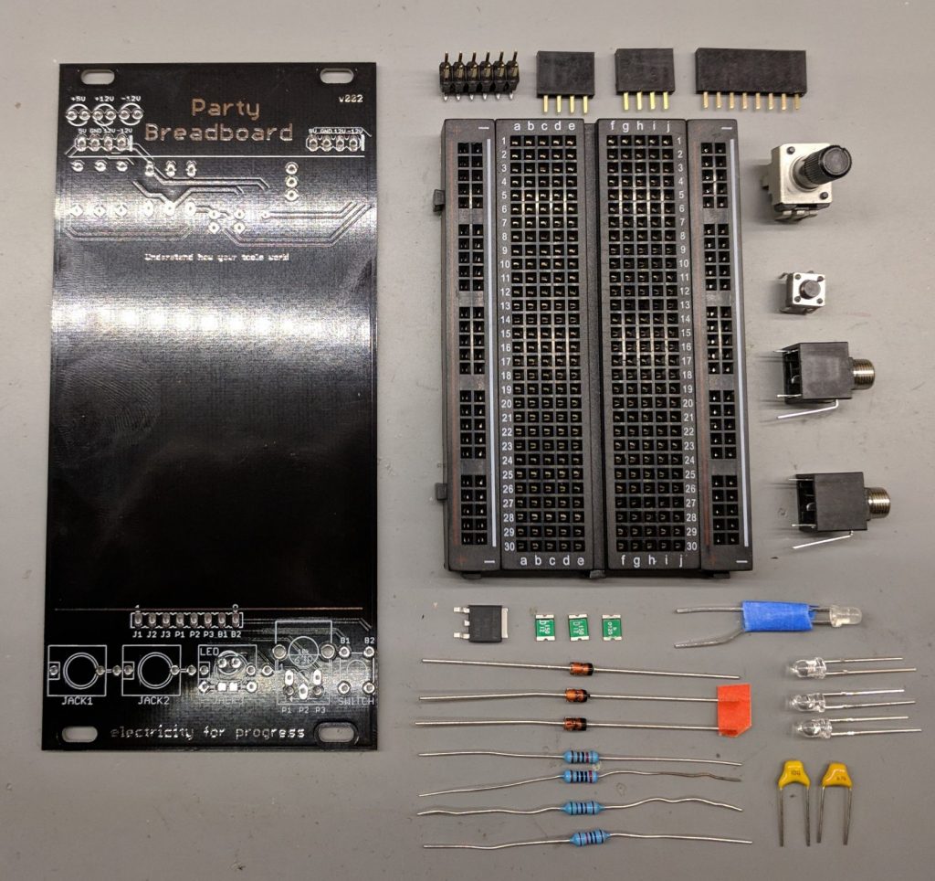
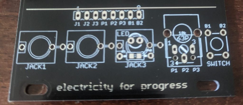
In this DIY build users have a variety of I/O options. The included three 3.5mm jacks along the bottom of the module easily patch signals to and from other modules, or one of the jacks can be exchanged for an indicator onboard LED! The board also has footprints for a variety of mini and 9mm potentiometers, allowing many different trimmer and small pots to be used. Finally a tactile switch sits to the bottom right corner.
Each of the I/O can be interfaced using the 8 pin jumpers at the bottom of the breadboard with J1/J2/J3 being the tip of each jack (the sleeve is grounded), P1/P2/P3 connected to the wiper and ends of the potentiometer, and B1/B2 attached to each side of the tactile button.
Power is provided on the back by a 10 or 12 pin connector, this should be a surface mount male header and you may need to ‘clip’ the small plastic tabs on header. The 5v rail can be engaged by closing the SJ1 jumper and including a 7805 regulator, or you can use 5v provided by the main skiff power supply using a 12 pin header. I tend to regulate my own 5v on each module, considering it is usually used for microcontrollers and sensitive devices. For protection there are include PTFE fuses on all three power rails in order to manage short circuits and zener diodes to dump excess voltages.
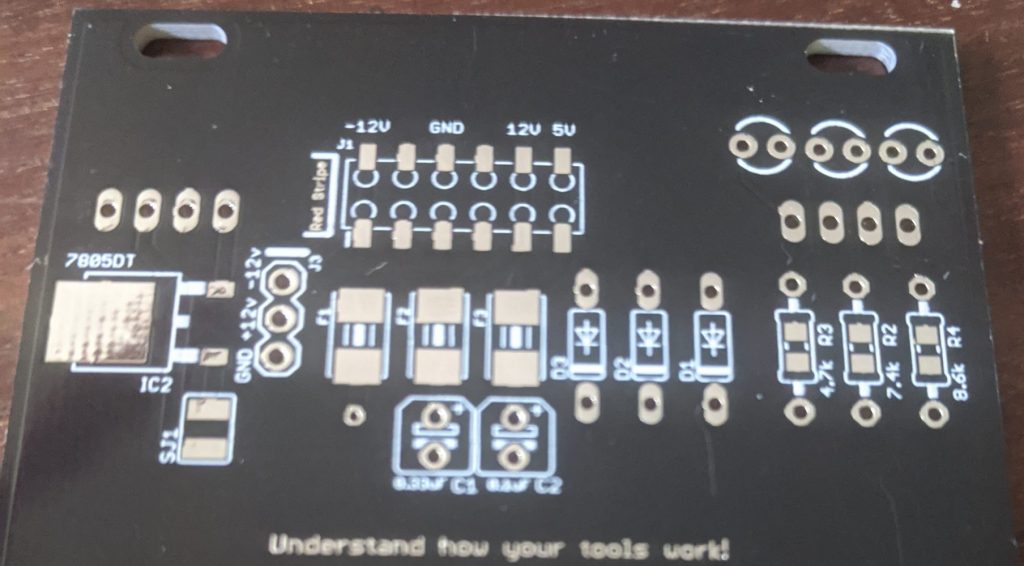
The LEDs on the front panel each have their cathode (negative/flat side) towards the right side edge from the front face of the panel, the LEDs go through the current limiting resistors and then to ground. Resistor values can be chose to taste, many prefer very dim LEDs for their modular systems (especially ‘always on’ indicators), I use a 10k trimmer pot to test the brightness of the LEDs before installation into the board… testing and choosing the indicator LED brightness is a great first project to use the Party Breadboard! Diodes D1 and D2 are 12v zener with D3 being 5.1v. Similarly F3 is a 5v fuse and F1/F2 are 12v fuses. The 7805DT regulator is a SMD package, but any 5v regulator could be hacked on, be sure to close Jumper SJ1 with a piece of wire to power the 5v regulator! Two capacitors are included to clean up the power lines around the regulator, if you are using 5v from the modular case then these caps can be excluded as well as exclude the 7805 and leave SJ1 jumper open.
This Schematic shows the simple routing from the jumper points and the power connections.
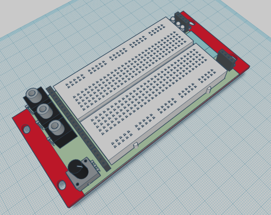
Tinkercad design for Party Breadboard
I like to draw up my modules in CAD in order to make sure everything fits between the rails, and to test out orientation of components. I created my own parts for the Pot, Thonk-style 3.5mm vertical jack, and the breadboard and LEDs I found in the Tinkercad.com library. https://www.tinkercad.com/things/gJaaTd4QUVj-party-breadboard-12hp/
Protected: Post Ideas
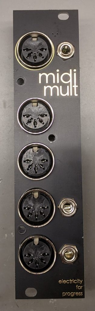
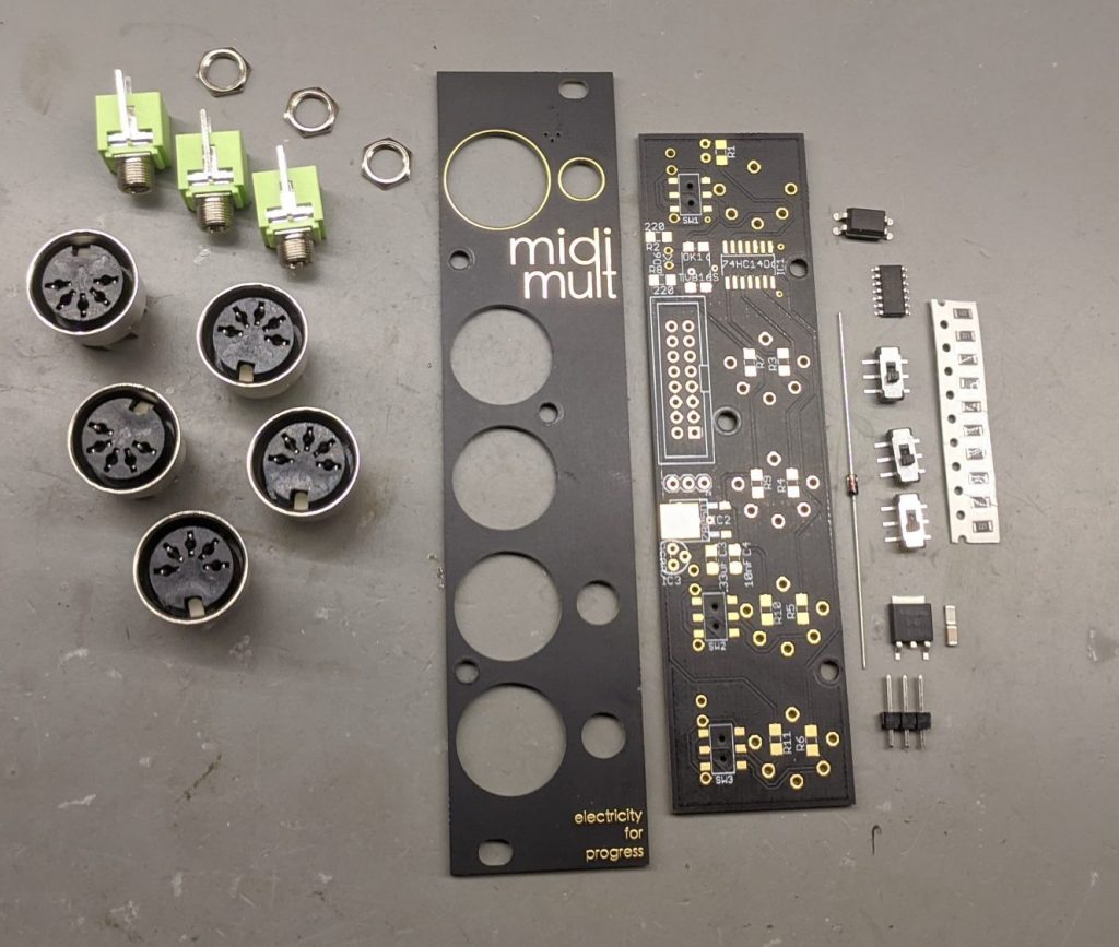
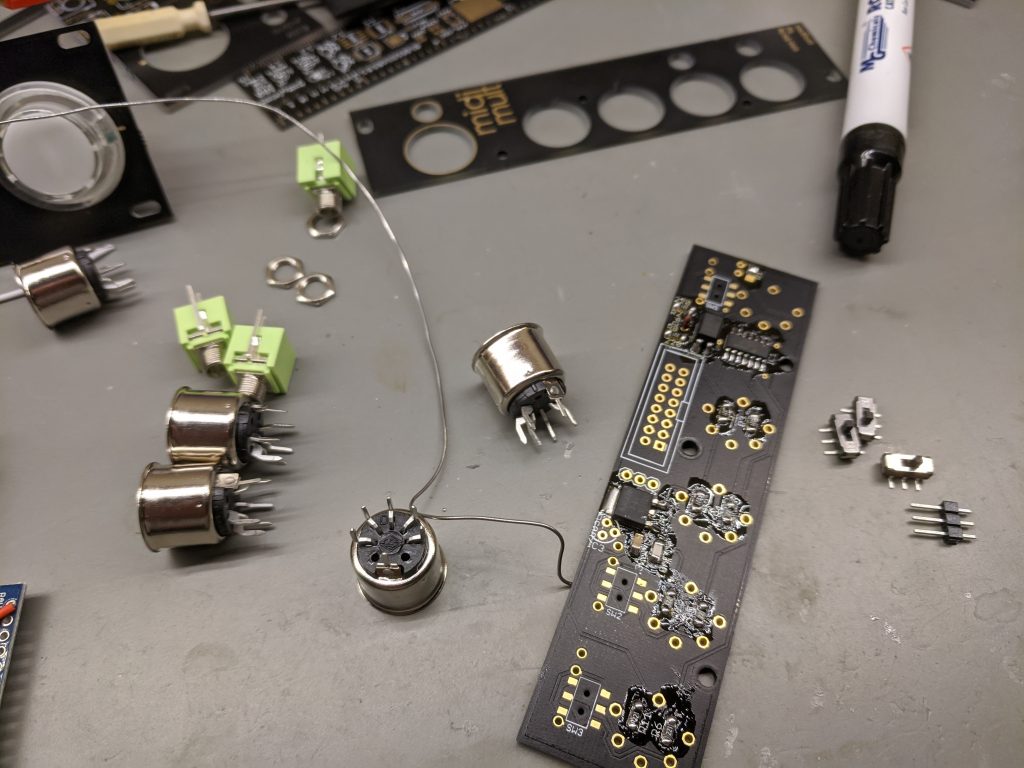
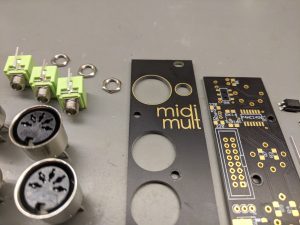
MIDI Mult
MIDImult – Route a single MIDI source from the top input jacks to four separate MIDI devices. Includes MIDI 5pin DIN jacks and accompanying (polarity switchable for TypeA and TypeB) 3.5mm jacks on Input and Outputs 3/4, allowing connection to Eurorack and other modern MIDI gear. This is a simple implementation of a 74HC14 MIDI Thru 1 x 4 circuit in Eurorack format. This unit is available on my Store fully assembled or as a kit, note the SMD parts are small but doable for an experienced builder.