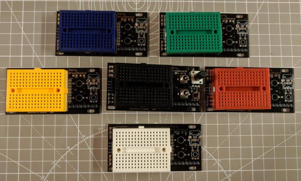
The same great prototyping experience of the full sized Party Breadboard, in super cute 1U format! Use this to spin up a quick schmidtt-trigger or 555 timer oscillator, try out a distortion circuit, or pop in a bunch of LEDs for a blinkenlight party! Available in both Pulp Logic and Intellijel formats, this board is made to fit many skiff. Purchase the Party Breadboard 1U in my store, and checkout the full sized Party Breadboard!
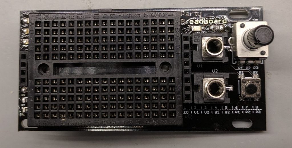

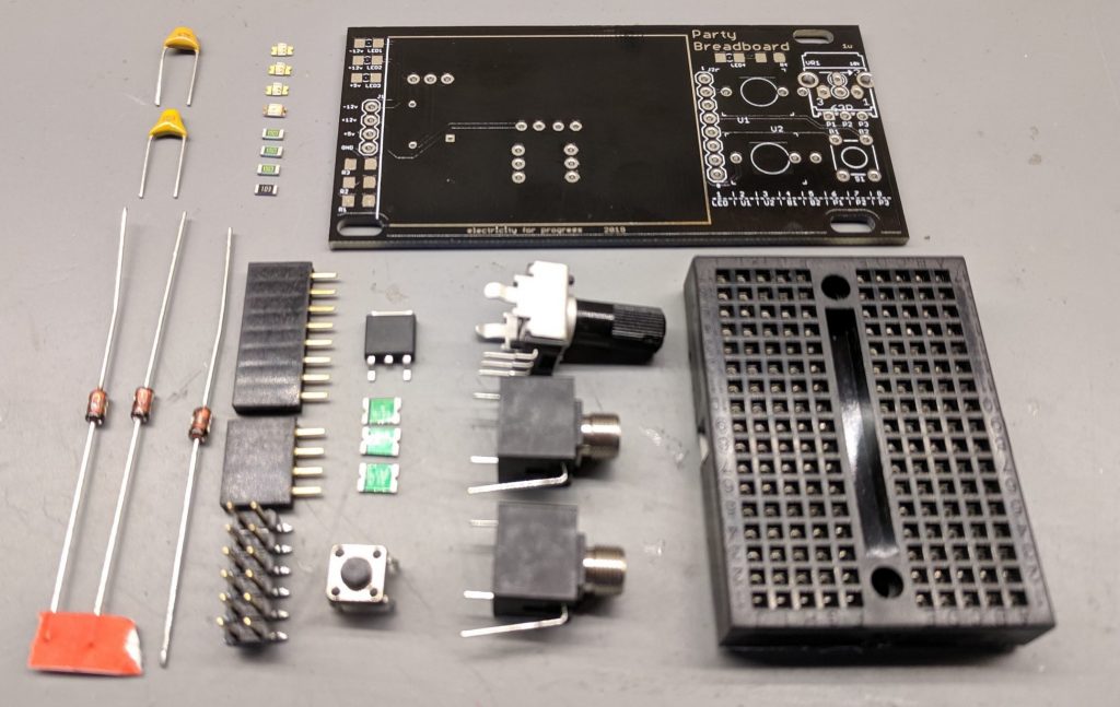
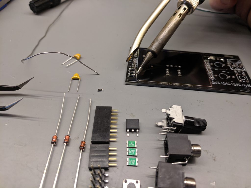
In this DIY build users have a variety of I/O options. The included three 3.5mm jacks easily allows signals to be patched across other modules. Along with an onboard indicator LED, the board also has footprints for a variety of mini and 9mm potentiometers, allowing many different trimmer and small pots to be used. Finally a tactile switch sits to the bottom right corner.
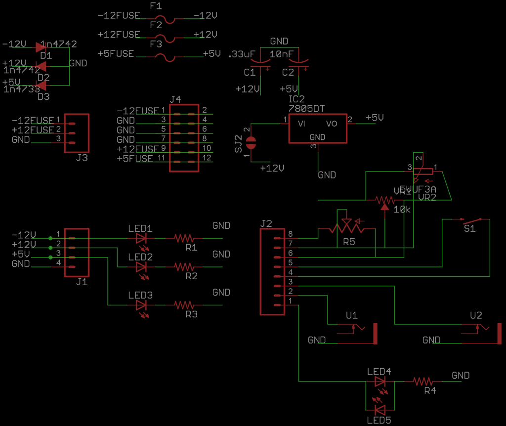
Each of the I/O can be interfaced using the 8 pin jumpers at the right of the breadboard with pin1 connected to the LED, U1/U2 connected to the tip of each jack (the sleeve is grounded), B1/B2 attached to each side of the tactile button and P1/P2/P3 connected to the wiper and ends of the potentiometer. A small legend for the pin connections is printed at the bottom of the module.
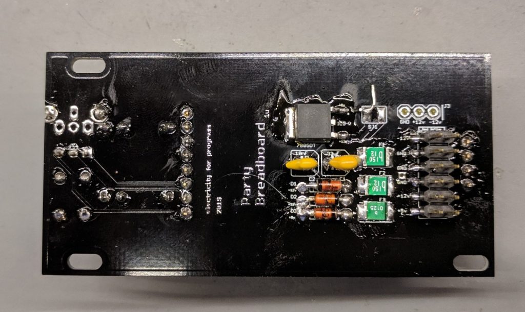
Power is provided on the back by a 10 or 12 pin connector, this should be a surface mount male header and you may need to ‘clip’ the small plastic tabs on header. The 5v rail can be engaged by closing the SJ1 jumper and including a 7805 regulator, or you can use 5v provided by the main skiff power supply using a 12 pin header. I tend to regulate my own 5v on each module, considering it is usually used for microcontrollers and sensitive devices. For protection there are include PTFE fuses on all three power rails (-12v,+12v,+5v) in order to manage short circuits and zener diodes to dump excess voltages.
The LEDs on the front panel each have their cathode (negative/flat side) towards the right side edge from the front face of the panel, the LEDs go through the current limiting resistors and then to ground. Resistor values can be chose to taste, many prefer very dim LEDs for their modular systems (especially ‘always on’ indicators), I use a 10k trimmer pot to test the brightness of the LEDs before installation into the board… testing and choosing the indicator LED brightness is a great first project to use the Party Breadboard! Indicator LEDs 4/5 allow two different color LEDs to be set with opposite polarity and makes it easy for a user to view the rough voltage (brightness) and polarity (color) of a CV signal.
Diodes D1 and D2 are 12v zener with D3 being 5.1v. Similarly F3 is a 5v fuse and F1/F2 are 12v fuses. The 7805DT regulator is a SMD package, but any 5v regulator could be hacked on, be sure to close Jumper SJ1 with a piece of wire to power the 5v regulator! Two capacitors are included to clean up the power lines around the regulator, if you are using 5v from the modular case then these caps can be excluded as well as exclude the 7805 and leave SJ1 jumper open.
This Schematic shows the simple routing from the jumper points and the power connections.